I have reached the stage of my electronics education where things are beginning to light up on purpose.
This is a meaningful improvement over the previous stage, where the soldering iron lit up in a way that did not seem entirely endorsed by the manufacturer.
The new soldering iron arrived, I finally assembled my 2025 B-Sides Canberra Amulet of Entry, and I started working through the second lesson in my electronics curriculum: oscilloscope basics. I am about halfway through that lesson so far. The actual oscilloscope part is next, but the FNIRSI DSO-TC4 has already earned its place on the bench as a component tester.
Also, I powered the amulet from my bench supply at 9 volts and did not blow it up. I am aware that "9 volt current" is not technically a thing. Current is amps; voltage is volts. I am becoming exactly annoying enough to notice this, which probably means the curriculum is working.
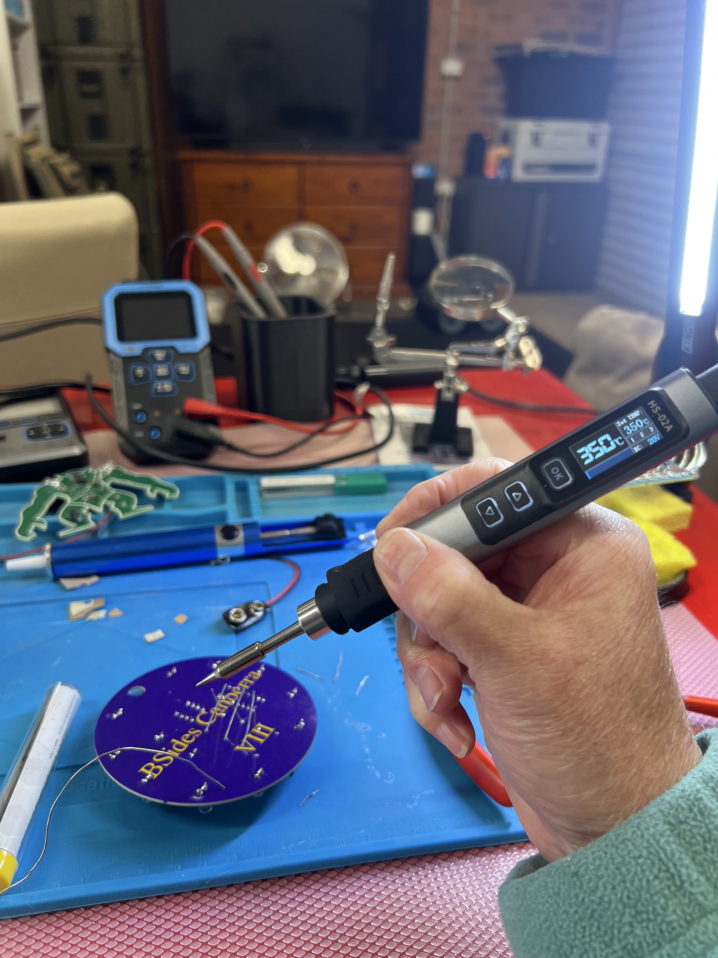
The new iron in action. The amulet survived, the desk survived, and I did not have to explain a scorch mark to anyone. Strong start.
The HS-02A Plot Twist
After the tragic little drama with my previous iron, I ordered a replacement and accidentally bought a different model from the same AliExpress listing.
The listing had both variants as options: HS-02A and HS-02B. I originally had the HS-02B. What arrived this time was the HS-02A.
This matters because the two are not just cosmetic variants. They are different enough that the tips are not compatible, which is exactly the sort of detail I am now learning to check after the parcel has already arrived.
The funny part is that the mistake worked out well. For the sort of through-hole beginner soldering I am doing right now, the HS-02A feels like the better choice. It is light, comfortable, and absurdly fast. Set it to 350 degrees C and it gets there in about five seconds. I am powering it from a standard HP USB-C supply, which has not blown it up yet. This is now a valid review category in my workshop.
I enjoyed using it more than I expected. Soldering had been sitting in my head as one of those mildly intimidating physical skills: hot metal, tiny pads, smoke, shame. In practice, with a decent iron, flux, a silicone mat, and the correct amount of patience, it was mostly just satisfying. The solder melts, flows, grabs the joint, and suddenly the abstract pile of parts becomes an object.
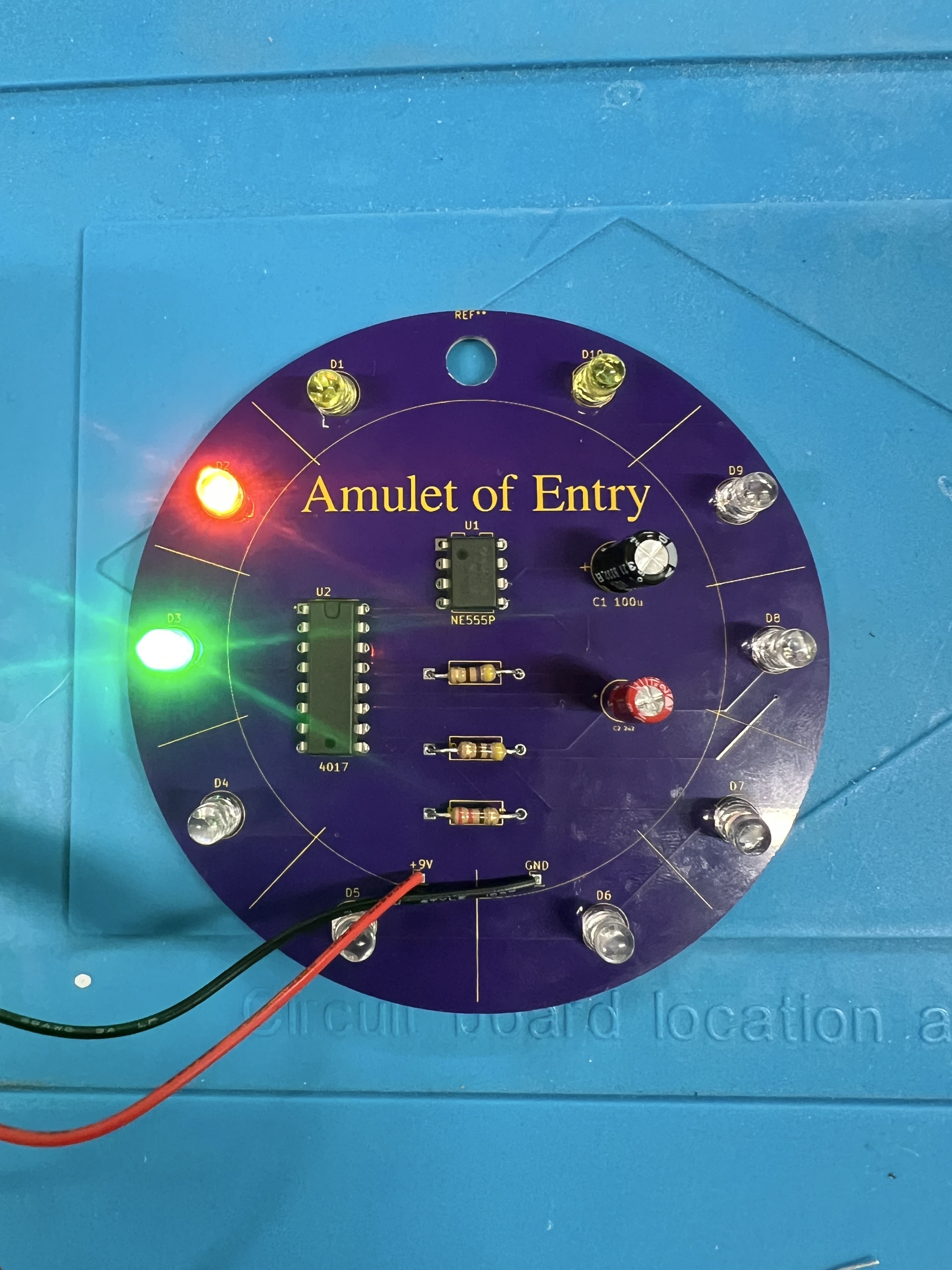
The Amulet of Entry lives. A 555 timer, a 4017 decade counter, capacitors, resistors, LEDs, and just enough ceremony to make it feel like a tiny cyberpunk friendship bracelet.
The Amulet Comes Alive
The B-Sides Canberra Amulet of Entry is a lovely beginner project because it is visible. There is a circular PCB, a ring of LEDs, a couple of ICs, a handful of passives, and a clear success condition: apply power and something should blink.
That kind of feedback is gold when you are learning. Software gives you error messages. Electronics gives you silence, heat, magic smoke, or, if you have been sufficiently polite to the electrons, light.
I used the bench power supply to feed the board at 9 V. After the soldering iron incident, I am much more respectful of the bench supply. It is not a magic box of safe electricity. It is a tool that will do exactly what I ask, including the stupid parts, unless I set sane limits and check my assumptions.
This time the result was pleasingly uneventful. The board powered up, the LEDs started doing their little sequence, and I got to enjoy the rare beginner electronics feeling of "that worked" without the immediate sequel, "why is that smell happening?"
The Component Tester Becomes A Friend
The second Phase Zero lesson is called Oscilloscope Basics, but the DSO-TC4 is not only an oscilloscope. It is a small three-in-one gadget: oscilloscope, signal generator, and component tester.
The component tester mode is the part I started with because it has an immediate beginner payoff. You put a mystery component in the socket or clips, press a button, and it tells you what it thinks it is.
For simple parts, this feels like cheating in the best possible way.
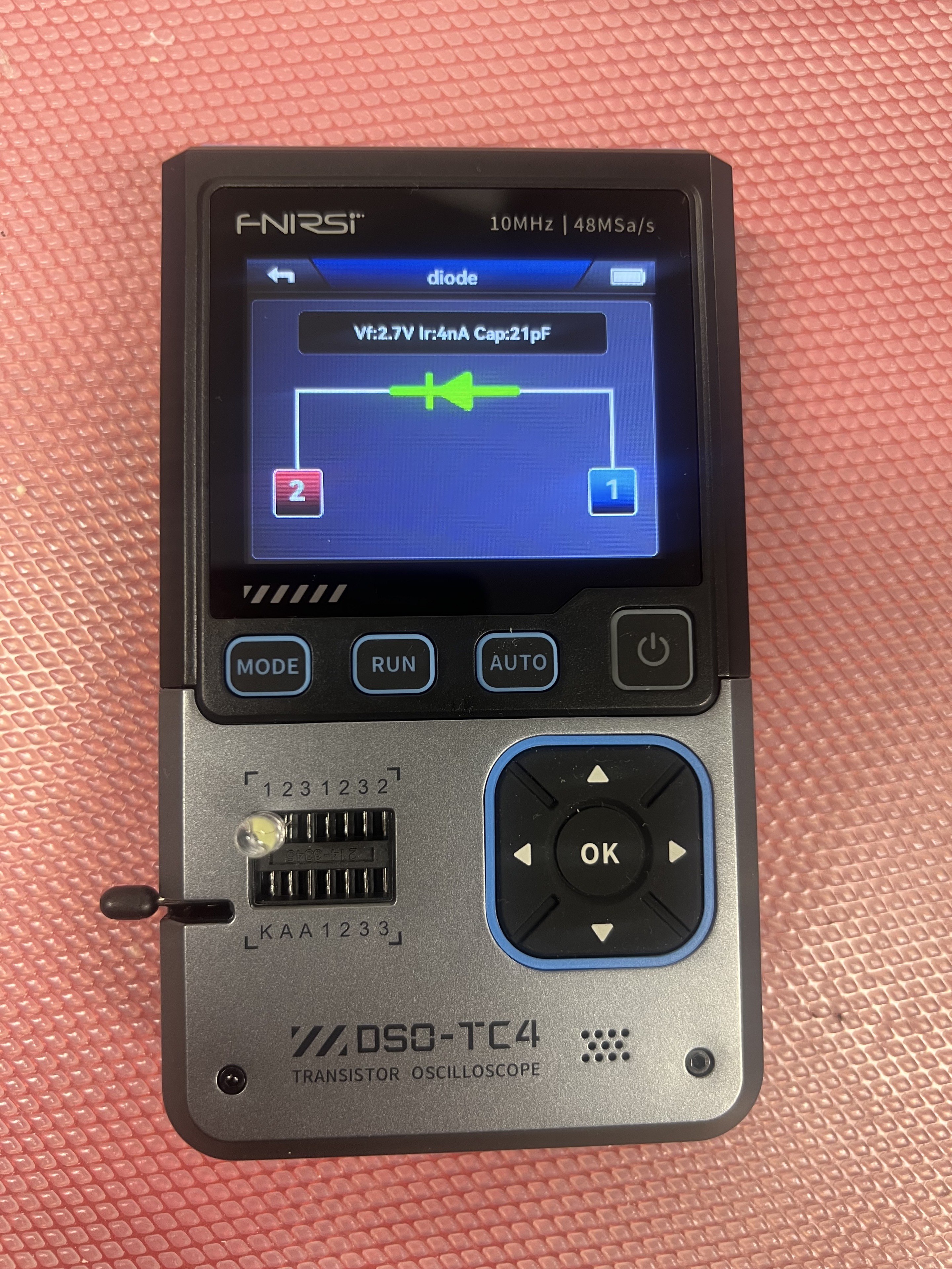
A good LED behaves like a diode. This one showed a forward voltage around 2.7 V. The suspicious LED that did not behave properly was sent to the small but growing pile of shame.
I now have a practical way to identify:
- Resistors
- Capacitors
- Diodes and LEDs
- NPN and PNP transistors
That last one is especially useful. A transistor is not just "the black three-legged thing". The tester can identify the type and show which leg is the base, collector, and emitter. That turns the component from a tiny riddle into something I can actually wire.
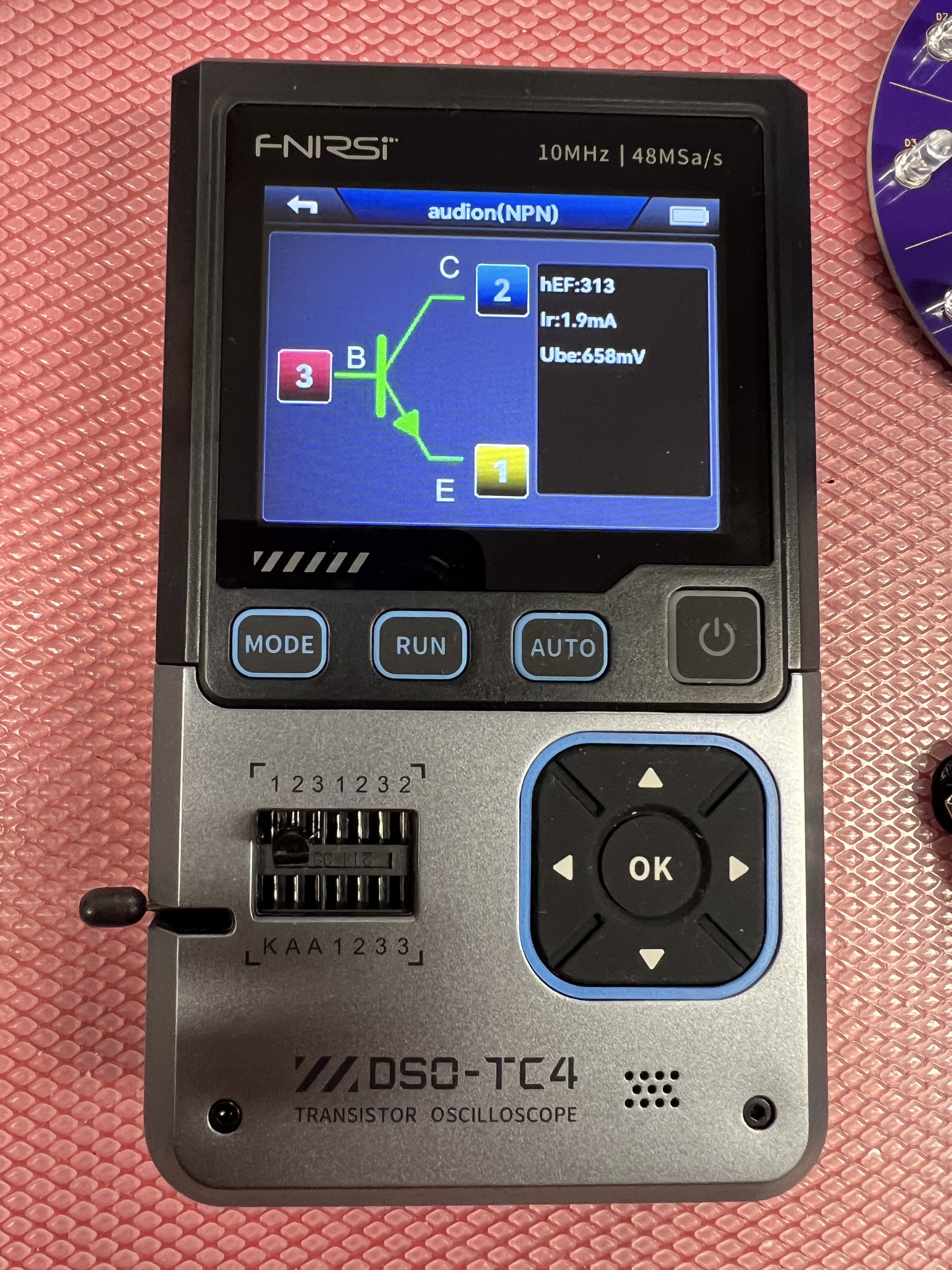
This NPN transistor came back with an hFE of 313 and a base-emitter voltage around 658 mV. I am not yet fluent in transistor, but I can now at least ask its name and which way it is facing.
The Box Of Tiny Black Mysteries
I also pulled out a box of ICs and started testing those.
This is where the DSO-TC4 stopped being a magical oracle and became a useful but limited instrument.
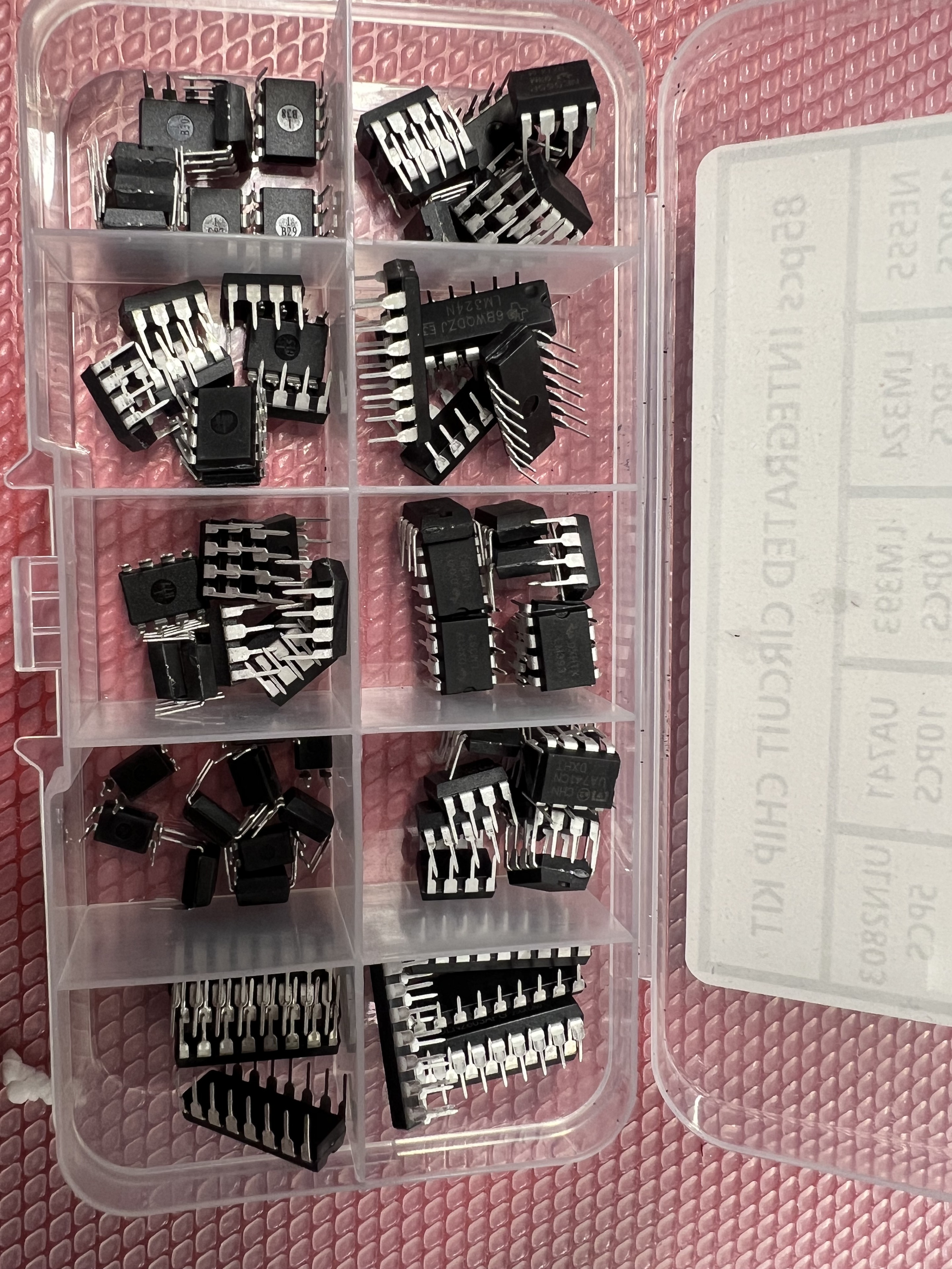
A box of chips. Or, from my beginner perspective, a box of tiny black rectangles covered in clues I do not yet know how to read.
An LM324N op-amp, for example, came back as Unknown/damaged.
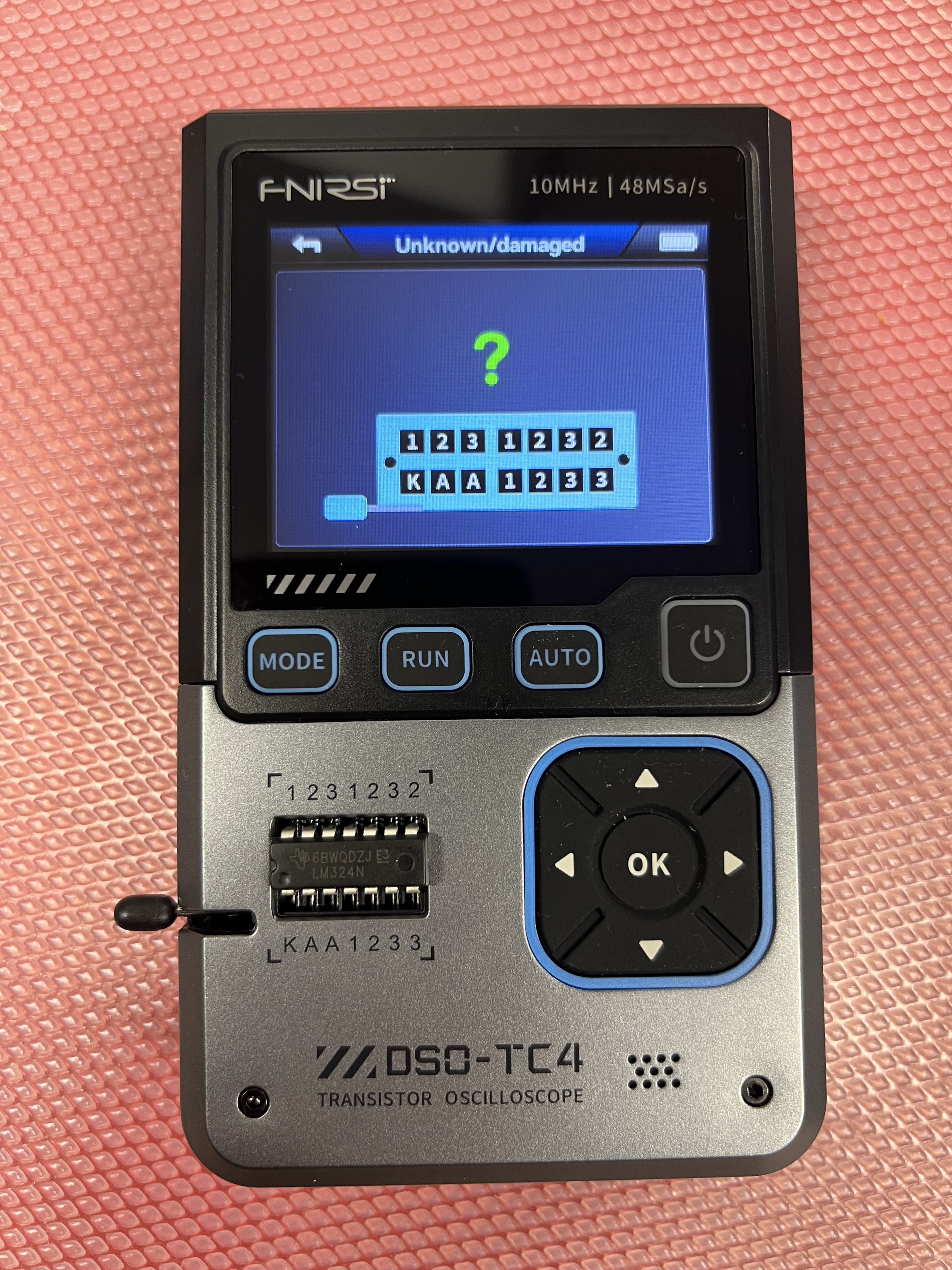
Important distinction: Unknown/damaged does not necessarily mean the chip is dead. It can also mean "this tester does not know how to analyse this kind of thing".
That was a useful lesson. A component tester can infer a lot from a passive component or a simple semiconductor junction. A resistor resists. A capacitor charges. A diode conducts in one direction. A transistor has junctions that can be probed and identified.
An integrated circuit is different. An op-amp is not one component in the same simple sense. It is a little circuit built inside a package, with power pins, input pins, output pins, internal transistors, biasing, protection structures, and behaviour that only makes sense when it is powered and used in a proper circuit.
So no, the DSO-TC4 cannot meaningfully analyse arbitrary integrated circuits just by putting the legs in the socket. For that I need the part number, the datasheet, the pinout, and a test circuit. This is less convenient than pressing AUTO, but probably better for my education and my ego.
Tolerances Are Not Lies
The other surprise was measurement variance.
Some resistors and capacitors did not measure exactly what was printed on the part or labelled in the kit. Not just a tiny rounding error either. I saw enough variation that 10 to 20 percent no longer feels shocking.
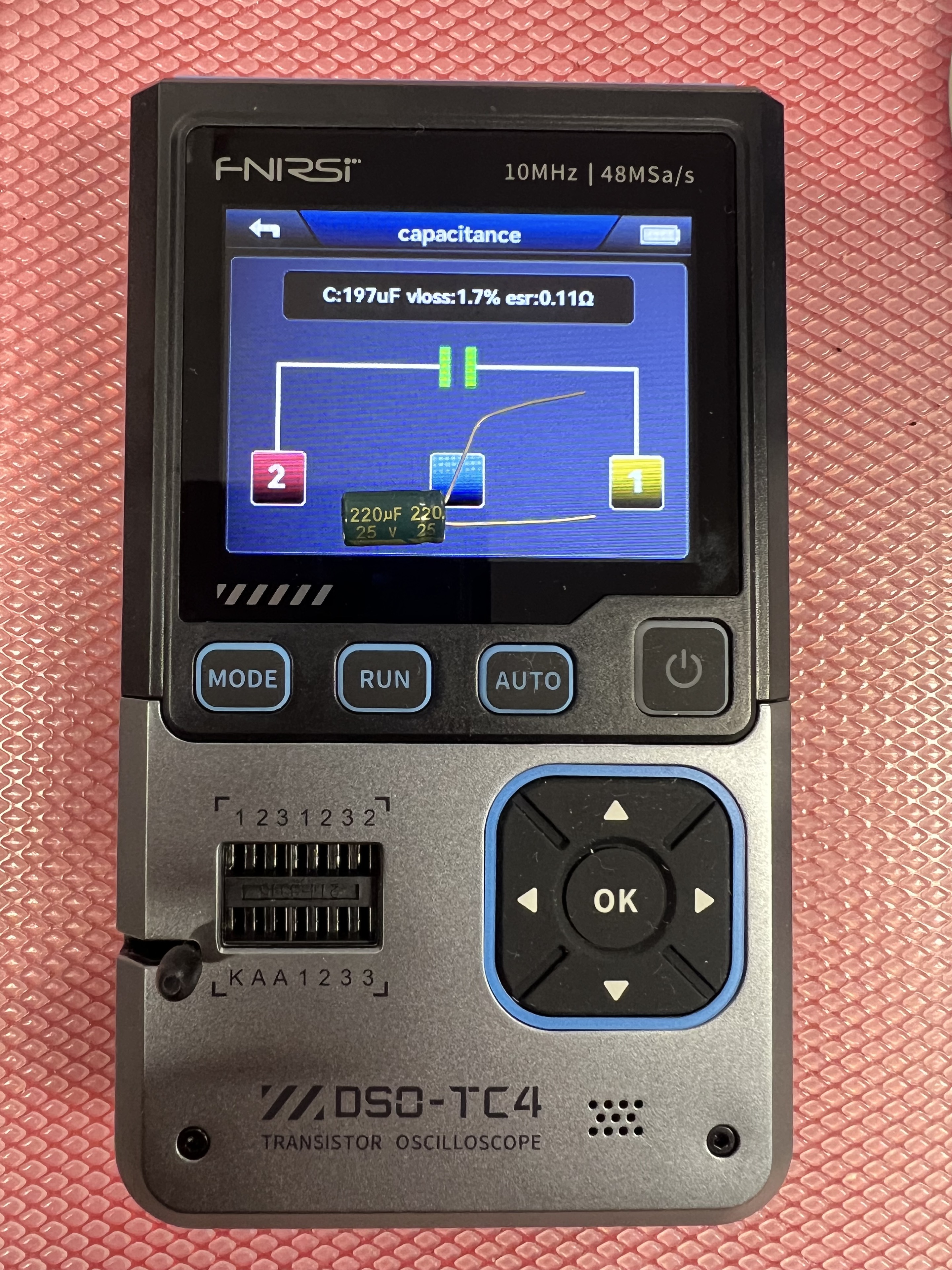
A 220 uF electrolytic measuring about 197 uF, with low ESR. That looks suspicious until you learn that many electrolytic capacitors have wide tolerances.
This was initially unsettling. The label says 220uF; the tester says 197uF. Somebody is lying, and I have only just met both of them.
The more boring and more useful answer is tolerance.
Many components are not manufactured to an exact value. They are manufactured to an acceptable range. A resistor might be 1 percent, 5 percent, or worse depending on its type and colour bands. Electrolytic capacitors can be much looser, and their measured value can vary with frequency, temperature, age, leakage, and the measurement method.
The tester itself is also not a calibration lab. Contact resistance, long leads, cheap sockets, component discharge state, and the instrument's own measurement approach all affect the result.
So I am trying to learn the right lesson: the DSO-TC4 is excellent for identification and sanity checks. It can tell me whether a part is roughly what I think it is. It can spot a dead LED. It can reveal a transistor pinout. It can show that a capacitor is in the right neighbourhood and whether its ESR looks concerning.
It is not the final judge of all electrical truth.
Where I Am In Lesson Two
At this point I am roughly halfway through the second lesson.
The component tester section has been excellent. I have turned a few drawers of anonymous parts into things with names. I can identify resistors, capacitors, diodes, LEDs, and transistors with much more confidence than I had last week. I also understand the first important boundary: simple components can be inferred; integrated circuits need context.
The next step is the actual oscilloscope function.
That means learning volts per division, time per division, triggering, and how to make a waveform stand still instead of skating across the screen like it has somewhere better to be. The lesson starts with the built-in square wave and then moves toward signal generator experiments and Arduino PWM. This is the bit I originally bought the DSO-TC4 for, and the bit I still mostly understand as "the screen draws a wiggly line that is trying to tell me something".
But that is the whole point of Phase Zero. A week ago, a multimeter was a yellow box of judgement. Now it is useful. A week ago, the DSO-TC4 was a gadget with too many modes. Now at least one of those modes has helped me diagnose a faulty LED and understand why an op-amp is not just a bigger transistor.
Progress is not glamorous. Sometimes it is a 220 uF capacitor reading 197 uF and me slowly learning not to take it personally.