My electronics education has produced its first casualty.
The victim was a FNIRSI HS-02B smart soldering iron. It cost about $50, had barely begun its working life, and is now refusing to turn its display back on. Its final performance was memorable: I looked down and found the soldering tip glowing bright orange.
That is not one of the advertised temperature settings.
I switched everything off immediately. Nobody was electrocuted, burned, or forced to explain a workbench fire to the insurance company (or more importantly, my wife). The damage appears limited to one inexpensive soldering iron, one thoroughly cooked tip, and a small amount of pride.
As electronics lessons go, $50 is not the worst tuition fee. Better to learn this near the start of the journey than after connecting a bench supply to something rare, expensive, or attached to a lithium battery.
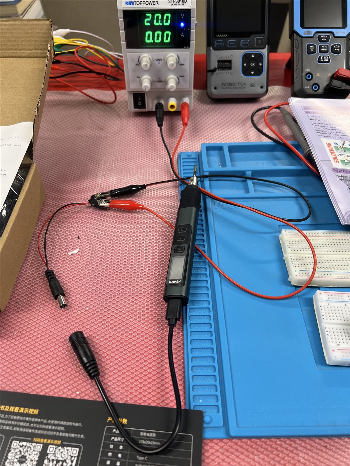
The scene after everything had been switched off. The supply is showing 20.0 V and 0.00 A because the load is disconnected.
What I Connected
The HS-02 is powered through USB-C. FNIRSI rates it for a working voltage of 9-20 V and a maximum power of 100 W. I did not have its normal fast-charge power adapter handy, but the kit included a cable with USB-C at one end and a female DC barrel connector at the other.
I also had a little 9V battery snap connected to a male barrel plug.
This led to the following magnificent, MacGyvered piece of engineering:
Bench supply
  -> banana leads
  -> alligator clips
  -> 9V battery snap
  -> DC barrel plug
  -> barrel-to-USB-C cable
  -> soldering iron
I set the bench supply to 20 V, connected the clips to the battery snap terminals, and turned it on. I had not set or checked the current limit. I did not even know what positions the current knobs were in.
For a brief period the arrangement appeared to work. Then the tip became an orange warning light.
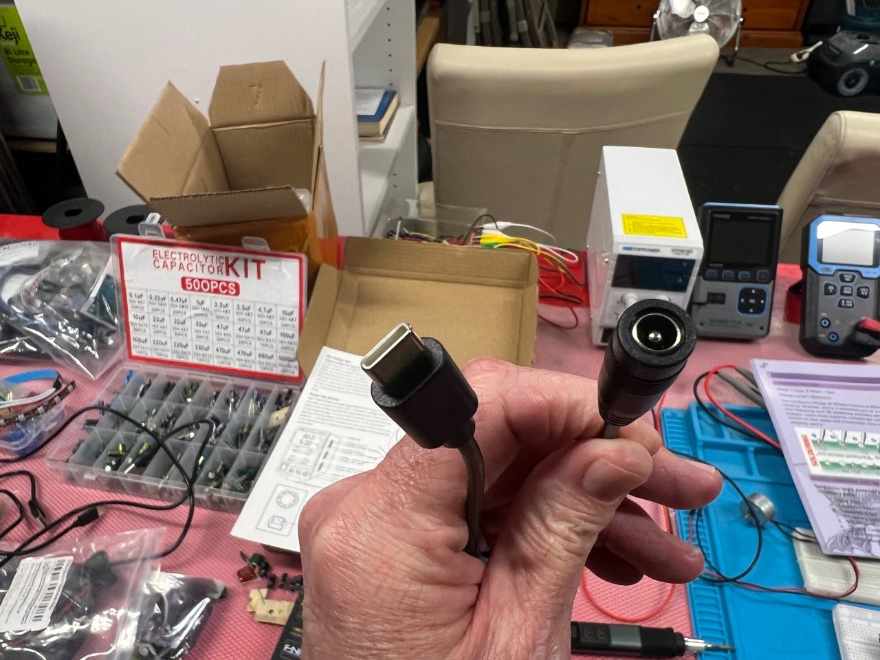
The barrel-to-USB-C lead. A USB-C connector does not automatically mean that USB Power Delivery negotiation is taking place.
The First Correction: A Power Supply Does Not Push Its Maximum Current
My first explanation was that I had sent 20 V and all 10 A from the bench supply straight into the iron. That is not quite how it works.
The bench supply sets a voltage. The connected load draws current according to its resistance and its electronic controls, up to the limit the supply allows. A supply capable of 10 A does not force 10 A through every device connected to it.
The current limit is a ceiling, not a current order.
That also explains why the supply displayed 0.00 A after I disconnected everything. The display shows current actually being drawn. With no load there is no meaningful current, regardless of where the current-limit knobs are set.
At full advertised power, the iron's expected numbers are easy to calculate:
Power = Voltage x Current
100 W = 20 V x 5 A
At 20 V, a 100 W iron can legitimately ask for approximately 5 A. My 0-30 V, 0-10 A supply had more than enough capacity to provide it.
This is an important qualification to the story: 20 V is within the manufacturer's stated range, and an unrestricted supply does not by itself explain why the tip glowed orange. A healthy iron should regulate its heater at that input voltage.
Not setting a current limit removed an important guardrail. It allowed a fault to receive as much current as the circuit demanded. But even a 5 A limit might not have stopped this particular runaway, because 5 A is inside the iron's normal full-power envelope. Current limiting protects against excessive current; it is not a replacement for temperature regulation.
What The Four Knobs Actually Do
My SKY TOPPOWER STP3010D has four adjustment knobs:
- Upper-right: coarse voltage
- Upper-left: fine voltage
- Lower-right: coarse current limit
- Lower-left: fine current limit
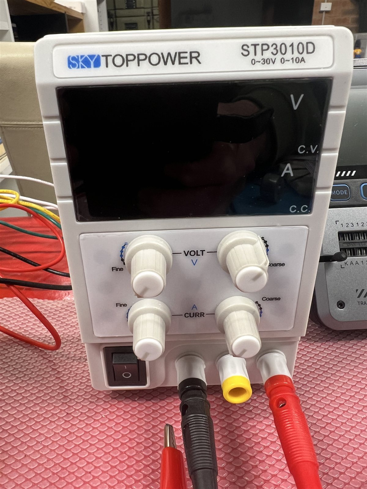
The labels were there all along. VOLT controls the output voltage; CURR controls the maximum current.
It operates in two modes:
- CV, or constant voltage: the load is drawing less than the current limit, so the supply maintains the selected voltage.
- CC, or constant current: the load wants more than the limit, so the supply reduces its output voltage to hold current at the selected maximum.
On this inexpensive analogue supply there is no separate output-enable button. The terminals become live when the main rocker switch is turned on, so wiring changes should be made with the supply switched off.
The standard way to preset its current limit is slightly strange the first time:
- Switch the supply off and disconnect the device.
- Turn both current controls fully anticlockwise.
- Turn the voltage down before making connections. A modest setpoint such as 5 V is enough for the test; exactly 0 V cannot drive the requested current.
- Connect positive and negative with a proper shorting lead rated for the expected current.
- Turn the supply on. It should enter
CCmode. - Slowly raise the coarse and fine current controls until the display shows the desired limit.
- Switch the supply off, remove the shorting lead, set the required voltage, and connect the load.
This deliberate short is only appropriate for a current-limited bench supply designed to tolerate it. It is not a general technique for batteries, wall adapters, USB chargers, mains power, or anything else that happens to have red and black wires.
For an unknown or possibly damaged circuit, the safer approach is to start with a low voltage and a low current limit, watch the current display, and increase cautiously. If the supply immediately enters CC, something is drawing more current than expected and it is time to stop and investigate.
USB-C Is A Connector; USB PD Is A Conversation
The USB-C socket gave me a false sense that the power side would take care of itself. With a proper USB-C Power Delivery charger, quite a lot does happen before 20 V appears on the cable.
USB-C uses its Configuration Channel pins, CC1 and CC2, to detect that a source and sink have been connected, determine cable orientation, and advertise basic current capability. A normal USB-C source begins with approximately 5 V on VBUS; it does not simply place 20 V there because a high-powered device might be connected.
USB Power Delivery adds a digital negotiation over the active CC wire. In simplified form:
Charger: Here are the voltage/current combinations I support.
Device:  I would like this one.
Charger: Accepted. I am changing the supply now.
Charger: The requested power is ready.
In protocol terms, the source sends its capabilities, the sink requests one of them, the source accepts, changes the output, and sends PS_RDY. Only then does the higher-voltage contract become active.
The contract does not mean the charger forces that current through the device. It means the device may draw up to the agreed amount. The same load-current rule still applies.
Cable capability matters too. The original USB PD 100 W ceiling used 20 V at 5 A, and 5 A operation requires a suitable electronically marked cable. Newer USB PD revisions can reach 240 W using higher voltages and appropriately rated cables. The USB Implementers Forum overview and USB Power Delivery specification library contain the decidedly less conversational version.
Quick Charge, which the HS-02 documentation also mentions, is a different fast-charging system with its own signalling. It should not be treated as another name for USB PD.
What My Direct-DC Cable Changed
A bench power supply has banana terminals, not a USB PD controller. It cannot advertise power profiles, receive a request, or negotiate a safe transition from 5 V to 20 V.
The barrel-to-USB-C cable supplied for direct-DC use bridges that gap mechanically and electrically. It may include simple identification components, but there is no USB PD source on the barrel side with which to negotiate. Whatever voltage the bench supply produces is already present for the adapter to deliver.
This does not automatically make direct DC an unsupported hack. FNIRSI explicitly specifies a 9-20 V working range and sells configurations intended for DC power. It does mean that the human operating the bench supply becomes the power policy manager.
I was responsible for checking:
- Voltage
- Current limit
- Polarity
- Connector rating
- Wire rating
- The condition of the load
The charger normally handles several of those questions before raising its output. I replaced that controlled exchange with, essentially, "Here is 20 V. Good luck."
Twenty volts was also the absolute top of the stated range. It was not technically over-voltage, but starting at the maximum left no margin for a poorly regulated turn-on, an accidental knob movement, contact bounce, or an adapter wired differently from my assumption.
The 9V Battery Snap Was Not A Converter
The battery snap deserves its own section because it was the weakest part of the arrangement.
It did not convert 20 V to 9 V. It did not regulate anything. It was just two thin wires connected to two shaped contacts and a barrel plug. The only conversion taking place was from one inconvenient connector to another.
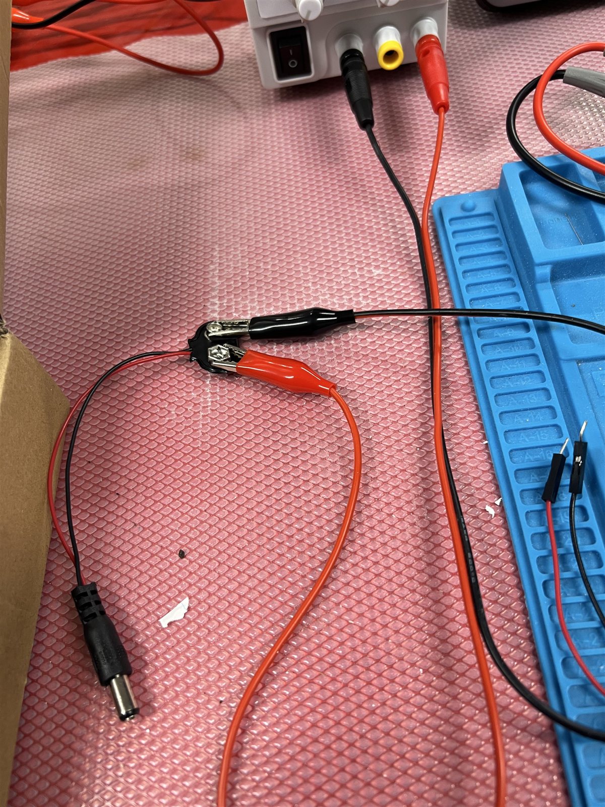
Red appears to follow the adapter's red wire and black follows black, but the exposed clips are uncomfortably close and the barrel's centre polarity still cannot be proved by colour alone.
There were several problems with this choice:
- Polarity was assumed: the visible red and black connections appear correct in the photograph, but I had not measured whether the barrel plug was centre-positive.
- The clips could touch: the exposed metal jaws were close together. A small bump could short the bench supply directly.
- The wire was too thin: a cheap 9V battery snap is not a sensible path for a possible 5 A load. Thin wire and small contacts add resistance, voltage drop, and heat.
- The contacts were temporary: alligator clips on battery snaps can move, arc, or make intermittent contact.
- Nothing was strain-relieved: one tug on the cable could alter the circuit while it was live.
A direct short between the alligator clips would not explain the glowing tip. It would bypass the iron and should force the supply into current-limit mode. The danger was still real: a 20 V supply capable of 10 A can put substantial heat into a misplaced wire or clip very quickly.
For this job I should have used a properly wired, adequately rated banana-to-barrel lead, verified centre-positive with a multimeter, or simply used the intended USB-C PD charger and a 5 A-rated cable.
So Why Did The Tip Glow Orange?
Honestly, I had NFI what was going on. The tip was glowing orange, the display was dead, and the iron was giving off a funny electrical-burn smell. I switched it off and asked Codex to help me make sense of what had happened.
The best explanation is that the temperature control stopped controlling. The tip had gone well beyond the iron's maximum specified temperature of 450 C, with something leaving the heater continuously powered. Possible causes include reversed polarity, a bad tip-sensor connection, a failed heater-control transistor, an intermittent connection, or simply a faulty iron.
There is no way I currently have the technical knowledge to open the handle, trace the board, and prove which one it was. The dead display and burnt-electronics smell strongly suggest that something inside was damaged. The missing current limit may have allowed the fault to continue at high power, but it was not necessarily what caused the original failure.
What I Will Do Differently
The replacement iron will not be introduced to the same adapter sculpture.
My new rules are:
- Use the intended USB-C PD charger and a properly rated cable whenever possible.
- Treat USB-C direct-DC adapters as electrical adapters, not magic safety devices.
- Verify barrel polarity with a multimeter before connecting a load.
- Use wiring and connectors rated for the expected current.
- Set the current limit before attaching an unfamiliar circuit.
- Start below the maximum voltage and raise it while watching both voltage and current.
- Stop immediately if the display is blank, the supply unexpectedly enters
CC, or anything heats that is not meant to heat. - Keep hot tools in a proper stand and never leave an energised test setup unattended.
I also now understand that a current limit is not a magic number that makes every experiment safe. It is one layer of protection. Correct voltage, polarity, wire size, connector choice, temperature feedback, and a functioning load all still matter.
A Useful $50 Failure
I would have preferred to learn this without turning a soldering tip into a tiny orange sun. On the other hand, the lesson is now thoroughly installed.
I understand the difference between voltage setting and current limiting. I know why an unloaded supply reads zero amps. I know how constant-voltage and constant-current modes interact. I understand that USB-C Power Delivery is a negotiated contract, not merely electricity emerging from an oval connector. I know that a 9V battery snap is not a power converter and should not be carrying five amps because it happened to fit the next adapter.
Most importantly, I learned to slow down and verify the boring assumptions before applying power.
Nobody was shocked. Nobody was burned. Nothing caught fire. It cost about $50, and the failure happened at the beginning of an electronics education rather than near the end of an expensive project.
The iron may be dead, but it has finally become educational equipment.
Next up: learning what an oscilloscope actually does. Hopefully I do not break that too.
References
- FNIRSI HS-02 product specifications
- USB-IF: USB Charger and USB Power Delivery
- USB-IF: USB Power Delivery specification library
- USB-IF: USB Type-C cable and connector specification